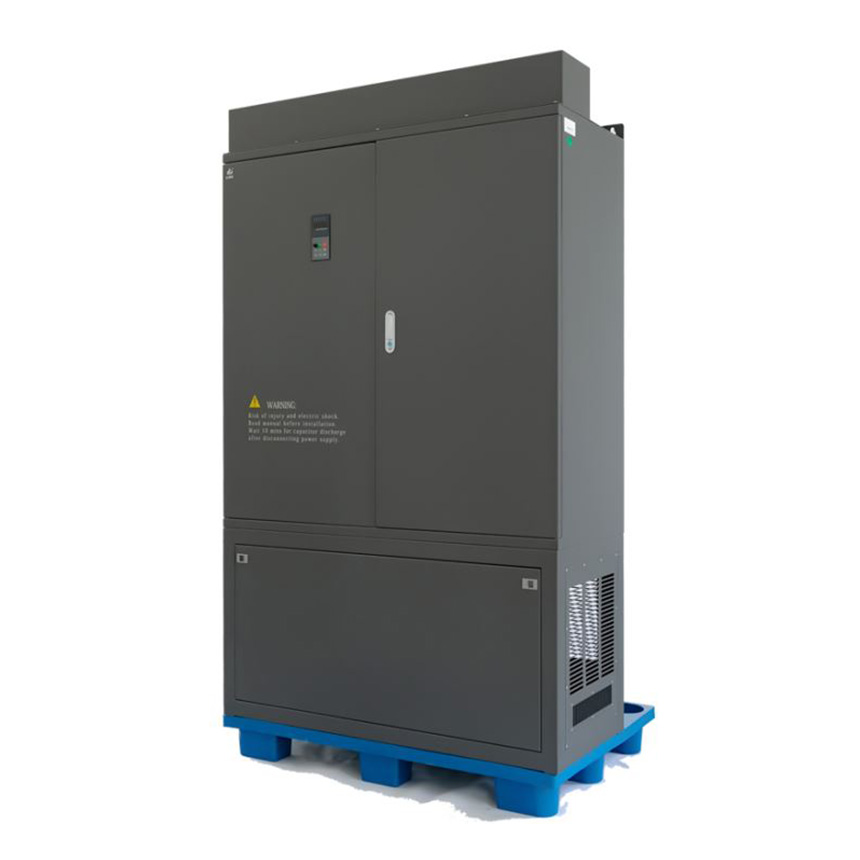
It has several advantages as following:
◇ Three-level drive technology, lower output harmonics, waveform closer to sine wave, lower motor heating, longer motor workinglife
◇ High performance for driving permanent magnet synchronous motor and AC asynchronous motor
◇ Compatible with 6 pulse, 12 pulse, 18 pulse, 24 pulse, multiple voltage input modes, allowing grid voltage range from 85% to 115%
◇ V/f control and high-performance vector control can be provided to achieve two-quadrant and four-quadrant operation, saving energy and reducing consumption;
◇ The larger starting torque to easy move the load, soft start and soft stop to eliminate the mechanical and electrical impact, to extend the service life of the equipment; 150% starting torque is available when 1Hz reaching.
◇ With CAN, Rs485 and other communication interfaces, it can realize communication with the host computer, realize the centralized control operation of multiple devices, and transfer the operation data to the ground dispatching room for remote supervision.
◇ Multi-channel digital, analog I/O interface
◇ Compatible with European control mode; capable of master-slave control of multi-machine dragging device
◇ Power balance during runing (no need to install encoder) and synchronous speed driving
◇ It has perfect protection functions such as overcurrent, overload, short circuit, phase loss, leakage lockout, overvoltage, undervoltage, overheating and other protection functions.
The main advantages of the three-level inverter:
1) Simple structure and small size;
2) Compared with the two levels, the device can achieve 2 times the voltage output with the same voltage level;
3) Reduce the common mode voltage of the motor;
4) Reduce common mode interference to the power grid;
5) It is convenient to realize the two-way flow of energy and the four-quadrant operation of the motor;
6) The output du/dt is reduced by half compared to the two levels;
7) Compared with the two levels, the number of phase voltage output levels increases and the output harmonics decrease.
Feature:
1. Substantial reduction of harmonic current on power source side
SD3200 suppresses the harmonics by using a multi-pulse diode rectification system (12 to 60 pulses),thereby substantially reducing the generation of harmonics in comparison with previous models. The harmonic generation level stipulated in IEEE 519 (1992) is satisfied. This inverter is ideal for power sources.

2. Total inverter effi ciency as high as approximate 97%
a). Because an output transformer is unnecessary, inherent losses are eliminated.
b). Multi-level PWM control minimizes switching loss.
c). Because the harmonic current on the power source side is reduced, the primary winding of the input transformer has a reduced harmonic losses.
Total inverter efficiency curve (including input transformer)
3. Source power factor as high as 95% or more
a). Due to full-wave rectifi cation with multi-phase diodes,operation is allowed with the source power factor (power factor on power source side) set at a high level.
b). A phase advancing capacitor and a DC reactor for improving the source power factor are unnecessary.
c). A smaller power capacity suffices for inverter operation.
4. High-reliability
a). Higher equipment reliability is achieved by reducing the number of inverter cells by using a single-phase,3-level inverter, etc..
b). Stable operation is maintained despite load fluctuations, by the simple sensor-less vector control function.
c). The control device has a 32-bit MPU for quick response and high-accuracy.
5. Vector control
Vector control with a speed sensor is available (as an option) for equipment having high speed and torque accuracy requirements. (option)
6. Easy maintenance
a). The inverter is air-cooled, requiring no cooling water.
b). Start/stop operation, parameter setting, fault display and data monitoring are performed on the touch panel with simple loader functions.
c). Simple, built-in auto-tuning functions facilitate testing and adjustment.
d). Fault diagnoses are easily performed.
e). A dry-type input transformer is adopted.
| Items | Specification | ||||
| Control mode | Control mode | V/F control | Sensorless Vector control 1 | Sensorless Vector control 2 | Close loop vector control |
| Starting torque | 1Hz 150% | 0.5Hz 150% | 0.25Hz 150% | 180% under 0Hz | |
| Speed adjust range | ** | 1:50 | 1:200 | 1:500 | |
| speed stabilizing | ±0.1% | ±0.3% | ±0.05% | ±0.02% | |
| precision | |||||
| Torque precision | NO | NO | Yes | Yes | |
| Motor type | General induction motor,permanent magnet synchronous motor (PMSM) | ||||
| Function design | Output volage | 3 electric level with low harmonic | |||
| Highest frequency | General vector control :400Hz V/f control:4000Hz | ||||
| frequency resolution | Digital setting: 0.01Hz analog setting: maximum×0.025% | ||||
| carrier frequency | 0.5K~16KHz, the carrier frequency can be adjust by temperature automatically | ||||
| Frequency reference setting method | Digital of Control panel, analog AI1, AI2, potentionmeter of control panel, UP/DN control, communication, PLC pulse frequency | ||||
| Accel./decel. characteristic | Linear curve and S curve accel. /decel. mode, range of time: 0.0 to 65000S. | ||||
| V/F curve | 3 mode: linear, multiple points, N Power | ||||
| V/F separation | 2 times separation: totally separation, half separation | ||||
| DC braking | DC braking frequency: 0.0 to 300Hz, DC braking current: 0.0% to 100% | ||||
| Braking unit | Built in braking unit up to 15kw, optional is 18.5kw to 75kw, external built in for above 93kw. | ||||
| Jog function | Job frequency range: 0.0 to 50.0Hz, the accel. and decel. time of Jog | ||||
| Configuration PID | Easy to perform pressure, flow, temperature close loop control | ||||
| PLC multiple speed | To achieve 16 segment speed running through built in PLC or terminal control | ||||
| Common Dc bus * | Multiple inverters use one DC bus for energy balance. | ||||
| Auto voltage regulation (AVR) | Enable to keep output voltage constant when grid fluctuation | ||||
| Over load tolerance capability | G type model: 150% rated current for 60s, 180% rated current for 2s, | ||||
| P type Model: 120% rated current for 60s, 150% rated current for 3s. | |||||
| stall control when over current, over voltage | Carry out limiting automation for running current, voltage to prevent over current, over voltage frequently | ||||
| Fast current limit function | minimize the IGBT module broken to protect the inverter, maximum reduce the over current fault. | ||||
| Torque limit and torque control | "Excavator" characteristics , torque limit automatically during motor running. Torque control is available in close loop vector control mode. | ||||
| Items | Specification | |
| features | friendly interface | Display Hello when power on. |
| Multiple function key MK.F button | It can set for Forward Jog, reverse Jog, forward/reverse switch | |
| Timing control function | A total running time and total running time calculating | |
| Motor over heat protection | Accepting motor temperature sensor signal input via AI1 terminals. | |
| Command source | Control panel, control terminals, series communication, switch freely. | |
| Frequency source | Digital setting, analog current/voltage, pulse setting, serial communication, main and auxiliary combination. | |
| Protection function | Short circuit detect after power on, input/output phase missing, over voltage, over current, under voltage, over heat, over load protection. | |
| Environment | Application site | Indoor, free of exposure to sunlight, no dusty, no corrosive, no inflammable gas, no oil and water vapor, and water dipping |
| Altitude | Lower 1000m | |
| environment temperature | -10℃~+40℃, power derated for 40~50℃, rated current derated 1% for 1℃increasing. | |
| Humidity | Less than 95%, no water condense. | |
| Storage | -40~+70℃ | |
SD3000-37G-T11-ASDA
SD3000 stand for products name
37G stand for rated of power, 37kw
T11 stand for input voltage range, T6: 3PH, 660VAC input, T11: 3PH, 1140VAC, T33: 3PH 3300VAC
ASDA stand for function description
| SD3000 series 1140V VFD model list | |||||||
| Series | Model list | Rated Power | Input current | Output current | Input reactor | DC Reactor | Output Reactor |
| 1 | SD3000-37G-T11-ASDA | 37 | 20 | 23 | 7.3mh/ 25A | 1mh/25A | |
| 2 | SD3000-45G-T11-ASDA | 45 | 26 | 28 | 5.6mh/ 32A | 0.8mh/28A | |
| 3 | SD3000-55G-T11-ASDA | 55 | 34 | 36 | 4.2mh/ 42A | 0.62mh/36A | |
| 4 | SD3000-75G-T11-ASDA | 55 | 47 | 50 | 3mh/ 58A | 0.45mh/50A | |
| 5 | SD3000-90G-T11-ASDA | 90 | 56 | 60 | 2.6mh/ 69A | 0.38mh/60A | |
| 6 | SD3000-110G-T11-ASDA | 110 | 68 | 73 | 2.2mh/ 85A | 0.3mh/73A | |
| 7 | SD3000-132G-T11-ASDA | 132 | 82 | 85 | 1.78mh/100A | 0.26mh/85A | |
| 8 | SD3000-160G-T11-ASDA | 160 | 98 | 104 | 1.5mh/ 120A | 0.22mh/104A | |
| 9 | SD3000-200G-T11-ASDA | 200 | 122 | 128 | 1.2mh/ 150A | 170mh/128A | |
| 10 | SD3000-250G-T11-ASDA | 250 | 150 | 160 | 0.97mh/ 185A | 140mh/160A | |
| 11 | SD3000-315G-T11-ASDA | 315 | 185 | 195 | 0.79mh/ 230A | 115mh/195A | |
| 12 | SD3000-400G-T11-ASDA | 400 | 235 | 250 | 0.62mh/ 285A | 90mh/250A | |
| 13 | SD3000-500G-T11-ASDA | 500 | 300 | 310 | 0.5mh/ 370A | 72mh/310A | |
| 14 | SD3000-560G-T11-ASDA | 560 | 355 | 350 | 0.22mh/ 355A | 64mh/350A | |
| 15 | SD3000-630G-T11-ASDA | 630 | 380 | 395 | 0.19mh/ 380A | 57mh/395A | |
| 16 | SD3000-710G-T11-ASDA | 710 | 430 | 450 | 0.17mh/ 430A | 50mh/450A | |
| 17 | SD3000-800G-T11-ASDA | 800 | 480 | 500 | 0.15mh/ 480A | 45mh/500A | |
| 18 | SD3000-1000G-T11-ASDA | 1000 | 600 | 520 | 0.12mh/ 600A | 36mh/620A | |
| SD3000 series 3300V VFD model list | |||||||
| Series | Model list | Rated Power | Input current | Output current | Input reactor | Output Reactor | |
| 1 | SD3000-800G-T33-ASDA | 800 | 166 | 173 | 1.2mH/170A | 0.6h/180A | |
| 2 | SD3000-1000G-T33-ASDA | 1000 | 208 | 216 | 1mH/210A | 0.48h/220A | |
| 3 | SD3000-1250G-T33-ASDA | 1250 | 259 | 270 | 0.8mH/260A | 0.39h/270A | |
| 4 | SD3000-1500G-T33-ASDA | 1500 | 311 | 324 | 0.67mH/320A | 0.32h/320A | |
| 5 | SD3000-2000G-T33-ASDA | 2000 | 415 | 433 | 0.5mH/420A | 0.24h/420A | |
| 6 | SD3000-3000G-T33-ASDA | 3000 | 623 | 649 | 0.34mH/630A | 0.16h/630A | |
| SD3000 series 6600V VFD model list | |||||||
| Series | Model list | Rated Power | Input current | Output current | Input reactor | Output Reactor | |
| 1 | SD3000-1000G-T66-ASDA | 1000 | 91 | 95 | 4mH/100A | 2mH/100A | |
| 2 | SD3000-1500G-T66-ASDA | 1500 | 114 | 119 | 3.3mH/120A | 1.6mH/120A | |
| 3 | SD3000-2000G-T66-ASDA | 2000 | 143 | 149 | 2.7mH/150A | 1.3mH/150A | |
| 4 | SD3000-2500G-T66-ASDA | 2500 | 171 | 178 | 2.2mH/180A | 1mH/180A | |
| 5 | SD3000-3000G-T66-ASDA | 3000 | 228 | 238 | 1.7mH/240A | 0.8mH/240A | |
| 6 | SD3000-5000G-T66-ASDA | 5000 | 342 | 357 | 1.1mH/360A | 0.6mH/360A | |
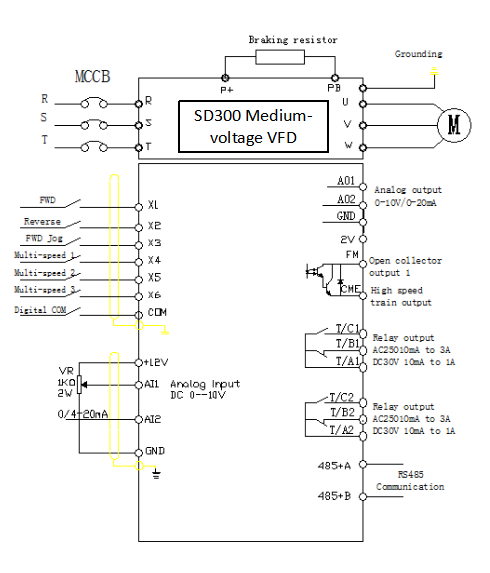
Multiple digital input, 2 analog input
2 analog output, 2 relay output, Rs485 and CAN bus interface
| Construction Materials | 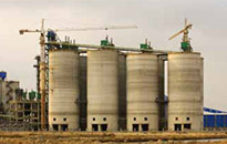 |
| √ Kiln head cooling fans | |
| √ Kiln tail heating fans | |
| √ Grinders | |
| √ Cement rotary kilns | |
| Petrochemical Mining | 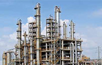 |
| √ Catalytic cracking unit | |
| √ Hydrogenation compressor | |
| √ Oil and gas transmission device | |
| √ Blowers/pumps/pelletizer | |
| Mining | 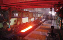 |
| √ Belt conveyers | |
| √ Grinders | |
| √ Mine air circulation blowers | |
| Iron and steel | 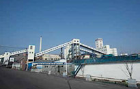 |
| √ Blast fumace blowers | |
| √ Primary/secondary dust blowers | |
| √ Dry quenched coke circulation blower | |
| √ High-pressure phosphorus ejector pump | |
| √ Blowers/water pumps | |
| √ Crusher | |
| Electric power | 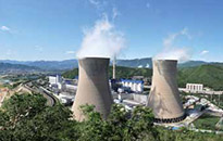 |
| √ Induced draft fan/forced draught fan | |
| √ Primary/secondary blowers | |
| √ Condensation pumps | |
| √ Recirculation pumps | |
| √ Feed pumps | |
| Others | 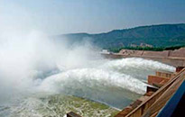 |
| √ Water conservancy, utilities (pumps) | |
| √ Sugaring (mill) | |
| √ Test crew | |
| √ Internal mixer |


