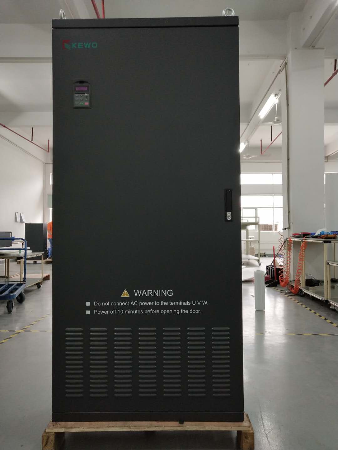
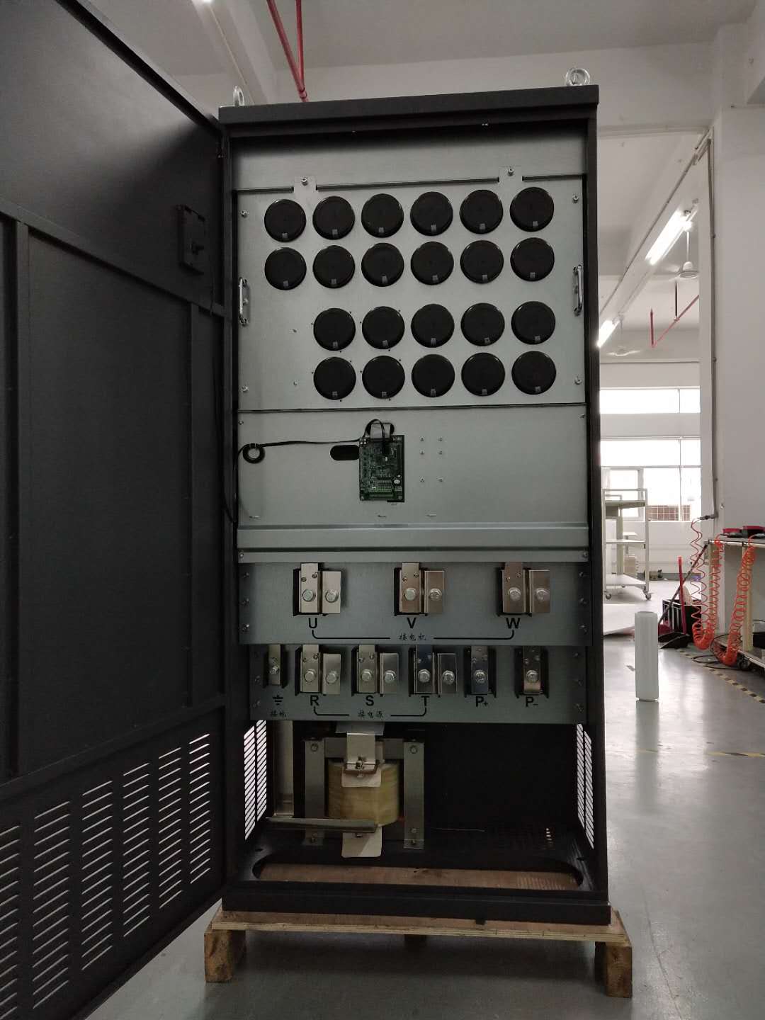
Product features:
1. Wide speed range: The 690V inverter allows for precise adjustments over a wide voltage range of 0-690V, and has a broad frequency range that can fully meet the speed requirements of motors under different working conditions, achieving continuous and stepless speed control.
2. High precision control: This inverter uses advanced control algorithms to ensure accuracy in motor speed control with a high adjustment precision of up to ±0.01%. It maintains stable performance whether running at low speeds or high speeds.
3. Strong overload capacity: The 690V inverter has excellent overload capacity and can withstand large overload currents in a short period of time, which effectively protects the motor during abnormal operating conditions and extends its lifespan.
4. Stable performance: We have used advanced heat dissipation designs and built-in multiple protection functions such as overcurrent, overvoltage and undervoltage, to ensure stable and safe operation even during long-lasting and high load operations.
5. Easy operation experience: The 690V inverter comes with an intuitive and user-friendly panel for easy parameter setting and operation control, and supports various communication protocols, making it convenient for users to communicate and achieve remote monitoring and control with the upper computer.
| Function Description. | Specification standard | |
| Input | Input voltage (V) | AC 3-phase 520V(-15%)~690V(+10%), rated voltage: 660V. |
| AC 3-phase voltage range 969V (-15%) to 1254V (+10%), rated voltage: 1140V. | ||
| AC three-phase voltage rated at 3300V with a range of 2805V (-15%) to 3630V (+10%). | ||
| Input frequency (Hz) | 50Hz/60Hz, allowable range 47-63Hz. | |
| Output | Output voltage (V) | 0 ~ Input voltage |
| Output frequency (Hz) | 0~650Hz | |
| Technical control performance. | Control mode | Space vector voltage control mode, sensorless vector control mode. |
| Type of motor | Asynchronous motor, permanent magnet synchronous motor Hz. | |
| Gearing ratio | Asynchronous motor 1:200 (SVC), permanent magnet synchronous motor 1:20 (SVC). | |
| Speed Control Accuracy | ±0.2%(No PG vector control) | |
| Speed fluctuation. | ±0.3%(No PG vector control) | |
| Torque response | <20ms(No PG vector control) | |
| Torque control accuracy | <10%(No PG vector control) | |
| Starting torque | Asynchronous motor:0.25Hz/150%(No PG vector control) | |
| Permanent Magnet Synchronous Motor:2.5Hz/150%(No PG vector control) | ||
| Overload capacity | 150%Rated current60s | |
| 180%Rated current3s | ||
| 200%Rated current1s | ||
| Operation control performance | Frequency setting method | Digital setting, analog setting, pulse frequency setting, multi-stage speed setting, simple PLC setting, PID setting, MODBUS communication setting, combination of settings that can be implemented and switching of setting channels. |
| Automatic voltage regulation function. | When the voltage of the power grid fluctuates, it is able to automatically maintain a constant output voltage. | |
| Fault protection function | It provides over-current, over-voltage, under-voltage, over-temperature, phase loss, overload and more than 30 other types of fault protection functions, can record the detailed operating status of the inverter during the fault, and has automatic fault reset function. | |
| Speed tracking restart function. | Achieve smooth non-impact starting for motors in rotation. | |
| Peripheral Interface | Resolution of Terminal Analog Input | Not greater than 20mV. |
| Terminal switch quantity input resolution | Not more than 2ms. | |
| Simulated input | 2 channels (AI1, AI2) 0-10V/0-20mA. | |
| Simulated output | 2 channels(AO1、AO2)0~10V /0~20mA | |
| Digital input | 5 ordinary inputs, maximum frequency 1kHz, internal impedance: 2.4kΩ. | |
| 1. Input impedance is high and the maximum frequency is 50kHz. | ||
| Digital Output | 2-channel high-speed pulse output, maximum frequency of 50kHz. | |
| 1. Route Y terminal open collector output. | ||
| Relay Output | Dual Programmable Relay Outputs | |
| TA1 public end TB1 normally closed TC1 normally open | ||
| TA2 common terminal TB2 normally closed TC2 normally open | ||
| Contact Capacity: 1A/AC250V, 1A/DC30V. | ||
| Other | Installation method | Supports three installation modes: wall-mounted, floor-standing, and flange-mounted. |
| Operating environment temperature. | -20~50℃: Use within this temperature range. 40℃ or above: Use with reduced capacity. | |
| Mean Time Between Failures (MTBF) | 2 years (at 25 degrees ambient temperature) | |
| Protection level | IP20 | |
| Cooling method. | Air-cooled Water-cooled | |
| AD1000-T6 series 660V VFD model list | |||||||
| Series | Model list | Rated Power | Input current | Voltage | Two/For quadrant | 2/3 level | Cooling type |
| 1 | AD1000-75G-T6-AEDA | 75 | 86 | 660V | Two quadrants | 2 level | FansCooling |
| 2 | AD1000-90G-T6-AEDA | 90 | 98 | ||||
| 3 | AD1000-110G-T6-AEDA | 110 | 120 | ||||
| 4 | AD1000-132G-T6-AEDA | 132 | 150 | ||||
| 5 | AD1000-160G-T6-AEDA | 160 | 175 | ||||
| 6 | AD1000-200G-T6-AEDA | 200 | 220 | ||||
| 7 | AD1000-250G-T6-AEDA | 250 | 270 | ||||
| 8 | AD1000-315-T6-AEDA | 315 | 350 | ||||
| 9 | AD1000-400-T6-AEDA | 400 | 430 | ||||
| 10 | AD1000-500-T6-AEDA | 500 | 540 | ||||
| 1 | AD1000-75G-T6-AERA | 75 | 86 | 660V | For quadrants | 2 level | FansCooling |
| 2 | AD1000-90G-T6-AERA | 90 | 98 | ||||
| 3 | AD1000-110G-T6-AERA | 110 | 120 | ||||
| 4 | AD1000-132G-T6-AERA | 132 | 150 | ||||
| 5 | AD1000-160G-T6-AERA | 160 | 175 | ||||
| 6 | AD1000-200G-T6-AERA | 200 | 220 | ||||
| 7 | AD1000-250G-T6-AERA | 250 | 270 | ||||
| 8 | AD1000-315G-T6-AERA | 315 | 350 | ||||
| 9 | AD1000-400G-T6-AERA | 400 | 430 | ||||
| 10 | AD1000-500G-T6-AERA | 500 | 540 | ||||
AD1000-37G-T6-ASDA
Product categories: AD1000 series, AD800 series.
2.Power:37G power 37KW
3.Voltage level:
T6: Three-phase 660V
T11: Three-phase 1140V
T33: Three-phase 3300V
4.Function differentiation:
First letter: A for air-cooled, W for water-cooled
Second letter: E for two-level, S for three-level
Third letter: D for two-quadrant, R for four-quadrant
Fourth letter: A for 6-pulse, B for 12-pulse, C for 18-pulse, D for 24-pulse.
For example, AD1000-200G-T6-ASDA means a 690V 200KW, two-level, two-quadrant drive.
Please contact us for further details.
Step 1: Installation
To begin, select a suitable location for installation based on the motor's requirements and the work environment. Ensure that the installation is secure and reliable. Next, refer to the provided wiring diagram and connect the power and motor wires correctly to ensure a safe and dependable electrical connection.
Step 2: Parameter Setting
Once installed, users can enter the parameter setting interface through the operation panel or communication protocol. Set appropriate parameters such as voltage, frequency, and speed based on motor requirements and the working environment. It's important to be cautious when setting these parameters since they directly affect motor performance and stability.
Following these simple steps, you can easily use the 690V inverter to drive your motor, achieving accurate speed control and efficient operation. Whether in industrial production, machinery manufacturing, or other fields, this inverter will provide you with an outstanding experience and reliable performance assurance.


